


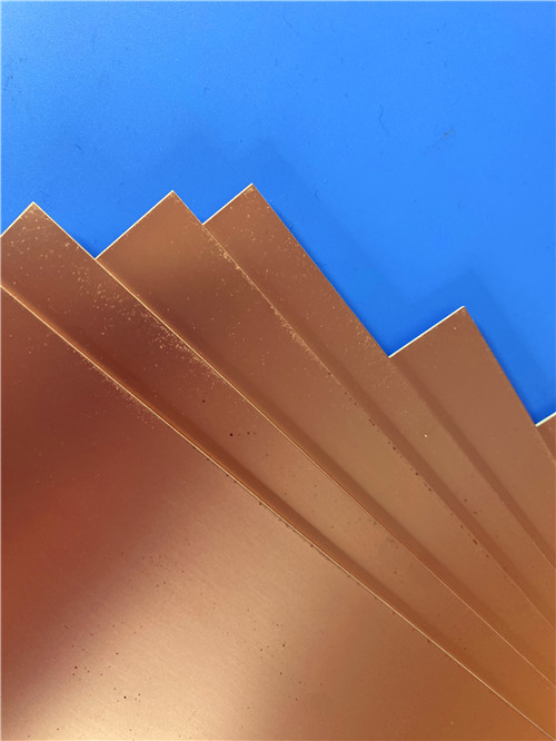

RT/duroid® matériau de remplacement? TLY-5 DK2.2 PCB stratifiés
ContPerson : Sally Mao
Numéro de téléphone : 86-755-27374847
Je suis désolé. : +8618277967574
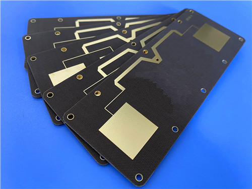
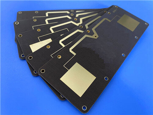
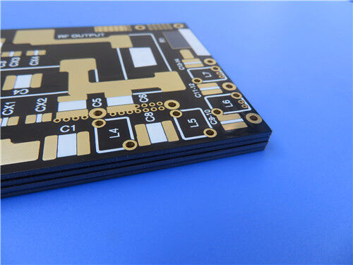
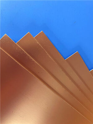
| Nom de marque: | Taconic | Numéro de modèle: | Le TLX-8 |
|---|
Description de produit
Il s'agit d'un substrat de micro-ondes en PTFE renforcé de fibre de verre à volume élevé fabriqué par AGC. Il a une constante diélectrique (Dk) de 2,55 ± 0,04 à 10 GHz. Le facteur de dissipation (Df) est de 0,0018 à 10 GHz.Il offre d'excellentes performances PIM (mesurées à moins de -160 dBc). Le matériau est dimensionnellement stable. Il a une très faible absorption d'humidité (0,02%). Il est classé UL94 V-0. Il convient aux conceptions micro-ondes à faible nombre de couches.Il est idéal pour les applications nécessitant un renforcement mécanique dans des environnements difficiles, y compris les applications spatiales, aérospatiales et de défense.
Quel PCB peut-on en construire?
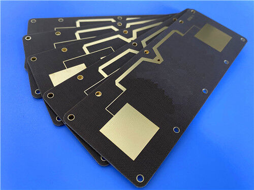
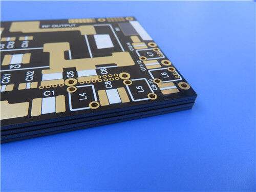
Une solution complète de PCB RF à 2 couches peut être fournie. La carte est basée sur le matériau TLX-8. L'épaisseur finie est de 0,85 mm. Le poids en cuivre est de 1 oz par couche.Le revêtement en or pur est appliqué comme finition de surface. Aucun masque de soudure n'est appliqué des deux côtés. Une sérigraphie blanche est imprimée sur la couche supérieure. La trace minimale et l'espace sont de 5 et 7 mil. La taille minimale du trou est de 0,3 mm. L'épaisseur du revêtement est de 20 μm..La norme de qualité est IPC Classe 2. Cette carte est idéale pour les antennes, les systèmes radar, les communications mobiles et les équipements de test à micro-ondes.
1. Vue d' ensemble du matériel
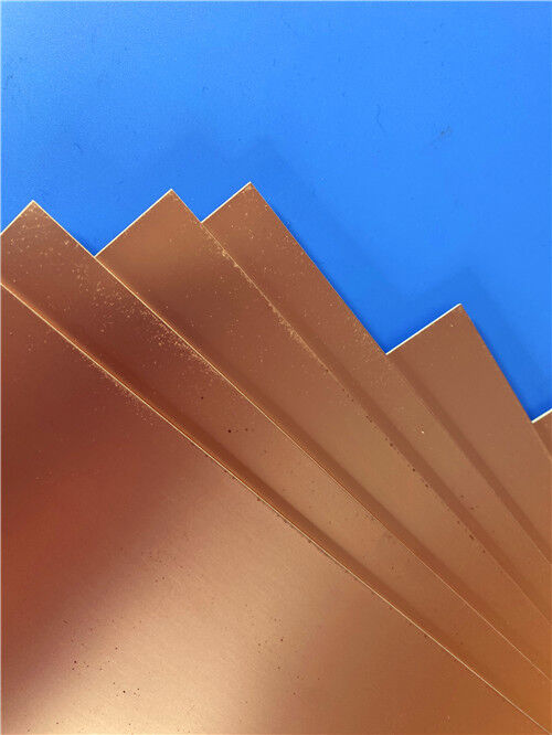
TLX-8 est un stratifié en fibre de verre PTFE. Il est fabriqué par AGC (anciennement Taconic).La matière est polyvalente.Il est disponible dans une large gamme d'épaisseurs et d'options de revêtement en cuivre.
Le matériau offre un renforcement mécanique, ce qui est important partout où un substrat subit des environnements difficiles.
Par exemple:
Résistance à la glissade pour les PWB boulonné à un boîtier qui rencontre des niveaux élevés de vibration lors du lancement spatial
Exposition à des températures élevées dans les modules du moteur
Résistance aux rayonnements dans l'espace (répertoriée par la NASA pour les faibles émissions de gaz)
Résistance aux environnements extrêmes en mer pour les antennes des navires de guerre
Résistance à une large plage de températures pour les substrats d'altimètre en vol
Le TLX-8 a une longue expérience dans l'espace.
Caractéristiques clés du TLX-8:
Laminat en fibre de verre PTFE
Dk faible et stable Dk est de 2,55 ± 0,04 à 10 GHz. La variation de Dk est d'environ ± 2% de -55 °C à 125 °C.
Facteur de dissipation faible Df est de 0,0018 à 10 GHz. La perte de signal est minimisée.
Performance PIM excellente PIM est mesurée à moins de -160 dBc. Ceci est essentiel pour les antennes de la station de base et les systèmes RF à faible distorsion.
Excellente stabilité thermique La température de décomposition (Td) est de 535°C (2% de perte de poids).
Stabilité dimensionnelle Le matériau est dimensionnellement stable. Après cuisson, MD est de 0,06 mm/m et CD est de 0,08 mm/m.
Le matériau est classé par la NASA comme ayant un faible dégagement de gaz.
Faible absorption de l'humidité: l'absorption de l'humidité n'est que de 0,02%, ce qui assure une performance stable dans des environnements humides.
2. feuille de données techniques TLX-8
| Les biens immobiliers | Valeur typique | Unités | Condition | Méthode d'essai |
| Constante diélectrique | 20,55 ± 0.04 | Je ne sais pas. | @ 10 GHz | IPC-650 2.5.5.3 |
| Facteur de dissipation | 0.0018 | Je ne sais pas. | @ 10 GHz | IPC-650 2.5.5.5.1 |
| Performance du PIM | < - 160 | dBc | 20 W par canal @ 800/1800 MHz | Mesure du coupon PCB |
| Dégazage (TML) | 0.03 | % | 4 H 257°F @ ≤5×10⁻⁵ Torr | Pour les produits de la catégorie 1 |
| Dégazage (CVCM) | 0 | % | 4 H 257°F @ ≤5×10⁻⁵ Torr | Pour les produits de la catégorie 1 |
| Dégazage (WVR) | 0.01 | % | 4 H 257°F @ ≤5×10⁻⁵ Torr | Pour les produits de la catégorie 1 |
| Résistance de surface (température élevée) | 6.605 × 10⁸ | Je vous en prie. | Je ne sais pas. | IPC-650 2.5.17.1 seconde 5.2.1 |
| Résistance de surface (condition d'humidité) | 3.550 × 10⁶ | Je vous en prie. | Je ne sais pas. | IPC-650 2.5.17.1 seconde 5.2.1 |
| Résistance au volume (température élevée) | 1.110 × 10¹⁰ | Mohm/cm | Je ne sais pas. | IPC-650 2.5.17.1 seconde 5.2.1 |
| Résistance au volume (condition d'humidité) | 1.046 × 10¹⁰ | Mohm/cm | Je ne sais pas. | IPC-650 2.5.17.1 seconde 5.2.1 |
| Stabilité dimensionnelle (MD ️ après cuisson) | 0.06 | mm/m | Je ne sais pas. | IPC-650 2.4.39 seconde 5.4 |
| Stabilité dimensionnelle (CD ️ après cuisson) | 0.08 | mm/m | Je ne sais pas. | IPC-650 2.4.39 seconde 5.4 |
| Stabilité dimensionnelle (MD √ contrainte thermique) | 0.09 | mm/m | Je ne sais pas. | IPC-650 2.4.39 seconde 5.5 |
| Stabilité dimensionnelle (CD) | 0.1 | mm/m | Je ne sais pas. | IPC-650 2.4.39 seconde 5.5 |
| Conductivité thermique | 0.19 | Nombre d'étoiles | Je ne sais pas. | Pour l'utilisation de l'unité de mesure de la qualité, les caractéristiques suivantes doivent être respectées: |
| Axe X de la CTE | 21 | en ppm/°C | 25 à 260°C | IPC-650 2.4.41 / ASTM D 3386 |
| CTE axe Y | 23 | en ppm/°C | 25 à 260°C | IPC-650 2.4.41 / ASTM D 3386 |
| CTE axe Z | 215 | en ppm/°C | 25 à 260°C | IPC-650 2.4.41 / ASTM D 3386 |
| Td (2% de perte de poids) | 535 | °C | Je ne sais pas. | IPC-650 2.4.24.6 (TGA) |
| Td (perte de poids de 5%) | 553 | °C | Je ne sais pas. | IPC-650 2.4.24.6 (TGA) |
| Résistance à la pellicule (1 oz ED) | 2.63 (15) | N/mm (lb/in) | Tension thermique | IPC-650 2.4.8 seconde 5.2.2 |
| Résistance à l'écaillage (1 oz RTF) | 2.98 (17) | N/mm2 (kpsi) | Je ne sais pas. | IPC-650 2.4.8 seconde 5.2.2 |
| Résistance à l' écaillage (1⁄2 oz ED) | 2.45 (14) | N/mm2 (kpsi) | Température élevée. | IPC-650 2.4.8.3 |
| Module de Young (MD) | 6, 757 (980) | N/mm2 (psi) | Je ne sais pas. | Pour l'utilisation dans les machines de traitement de l'air |
| Le module de Young (CD) | 82,274 (1 200) | N/mm2 (psi) | Je ne sais pas. | Pour l'utilisation dans les machines de traitement de l'air |
| Absorption de l'humidité | 0.02 | % | Je ne sais pas. | IPC-650 2.6.2.1 |
| Décomposition diélectrique | > 45 | KV | Je ne sais pas. | IPC-650 2.5.6 |
| Indice de flammabilité | V-0 | Je ne sais pas. | Je ne sais pas. | L'utilisation de l'équipement |
3Principaux avantages du TLX-8
|
Caractéristique |
Avantages |
|
Dk est égal à 2,55 ± 0.04 |
Une tolérance stricte permet un contrôle d'impédance cohérent |
|
Df est 0,0018 à 10 GHz |
Une faible perte minimise l'atténuation du signal dans les circuits à micro-ondes |
|
PIM est < -160 dBc |
Excellente performance à faible distorsion pour les antennes de la station de base |
|
Td est > 535°C |
Une résistance exceptionnelle à la décomposition thermique est fournie |
|
L'ETC X/Y est de 21/23 ppm/°C |
Une bonne stabilité dimensionnelle est obtenue |
|
Faible dégazage (TML 0,03%) |
Liste de la NASA pour les applications spatiales |
|
L'absorption d'humidité est de 0,02% |
Une très faible absorption de l'eau assure une performance stable dans des environnements humides |
|
La cote UL94 V-0 est atteinte |
Le respect de la sécurité incendie est assuré |
|
Large plage d'épaisseur (0,064-6,35 mm) |
La flexibilité de conception est activée |
|
La production en grande quantité est soutenue |
Matériau d'antenne rentable |
4. Champs d'application
TLX-8 est utilisé dans de nombreuses applications RF et micro-ondes exigeantes:
- systèmes de radar
- les communications mobiles
- équipement d'essai au micro-ondes
- appareils de transmission à micro-ondes
- couples, séparateurs, combinateurs, amplificateurs, antennes
5. PCB RF à 2 couches personnalisé Spécification complète
Une solution complète de PCB RF à 2 couches peut être fournie sur la base de TLX-8.
Caractéristiques du tableau
| Spécification | Détails |
| Type de plaque | PCB RF à deux couches |
| Matériau de base | TLX-8 (0,762 mm / 30 millilitres de noyau) |
| Épaisseur du panneau fini | 0.85 mm |
| Poids du cuivre fini | 1 oz (35 μm) par couche |
| Dimensions du tableau | 76.4 × 98,6 mm (1 pièce) |
| Tolérance de dimension | ± 0,15 mm |
| Trace minimale / espace | 5 / 7 millilitres |
| Taille minimale du trou | 0.3 mm |
| Via épaisseur de revêtement | 20 μm |
| Finition de surface | Plaqué en or pur |
| Masque de soudure supérieur | Je ne veux pas. |
| Masque de soudure inférieure | Je ne veux pas. |
| Le haut de la sérigraphie | Blanc |
| Vêtements de soie de fond | Je ne veux pas. |
| Classification IPC | Classe 2 |
| Format de l'œuvre | Le Gerber RS-274-X |
| Tests | Test électrique à 100% (avant expédition) |
| Disponibilité | Dans le monde entier |
6Pourquoi l' or pur est utilisé
Pour ce PCB RF, on choisit le plaquage en or pur. Les avantages sont énumérés ci-dessous.
| Avantages | Avantages |
| Une excellente soudabilité est assurée | Une surface exempte d'oxydation est disponible pour le montage des composants. |
| Le câblage est pris en charge. | Les composants RF qui nécessitent une liaison au fil d'or peuvent être utilisés |
| La résistance à la corrosion est assurée | Les traces de cuivre sont protégées dans des environnements hostiles |
| Une faible résistance au contact est obtenue | Ceci convient aux connecteurs de bord et aux points d'essai |
| Une longue durée de conservation | La soudabilité est préservée pendant de longues périodes |
7Pourquoi aucun masque de soudure n' est utilisé
| Avantages | Avantages |
| Le poids est réduit | Des planches minces et légères sont réalisées |
| Le coût est réduit | L'application du masque de soudure est éliminée |
| Les performances RF sont optimisées | Le masque de soudure peut affecter l'impédance et introduire des pertes à haute fréquence |
| La mise à la terre en cuivre nu est autorisée. | Des connexions de mise à la terre directes peuvent être effectuées |
| La vérification visuelle est simplifiée | Les traces et les tampons sont clairement visibles. |
Q1: Quelle est la constante diélectrique de TLX-8?
Le processus Dk est de 2,55 ± 0,04 à 10 GHz. La variation de Dk est d'environ ± 2% de -55 °C à 125 °C. Ce Dk stable permet un contrôle d'impédance constant.
Q2: Quelle est la performance PIM du TLX-8?
Le PIM est mesuré à moins de -160 dBc. Cette mesure est effectuée à l'aide d'un coupon PCB fabriqué.Cette excellente performance PIM rend TLX-8 idéal pour les antennes de la station de base.
Q3: Le TLX-8 est-il adapté aux applications spatiales?
Oui. TLX-8 a une longue expérience spatiale. Il est répertorié par la NASA pour ses faibles dégagements. Les valeurs de dégagement sont de TML 0,03%, CVCM 0,00% et WVR 0,01%.et autres applications spatiales.
Q4: Quelles sont les épaisseurs disponibles pour le TLX-8?
Le TLX-8 est disponible dans des épaisseurs allant de 0,064 mm (0,0025") à 6,35 mm (0,250").Les tailles de panneau standard comprennent 18" × 24" (457 mm × 610 mm) et d'autres tailles jusqu'à 36" × 48".
Q5: Où peut-on obtenir la fiche de données officielle TLX-8?
La feuille de données officielle est disponible auprès d'AGC (anciennement Taconic). Le courriel de contact est agc-ml.info-maltimaterial@agc.com. Notre équipe peut également fournir la documentation.
Prêt à commencer?
Le laminat brut TLX-8 peut être fourni. Des PCB RF à 2 couches entièrement fabriqués avec une finition en or pur et une capacité de ligne fine peuvent être fabriqués.
Contactez-nous dès aujourd'hui pour:
Prélèvement et essais de matériaux
Aide à la conception de circuits RF
Calcul de l'impédance et soutien à la conception
Cité des PCB et examen du DFM
Assistance technique pour votre application spécifique
Entrez votre message

RO4350B, 4003C ; Rogers 5880, 5870, 6002, 6010, 6006, 6035 ; RO3003, RO3035, RO3006, RO3010, RO3210, RO3203
TLX-8, TLX-6, TLX-9, TLX-0, TLX-7, TLY-3, TLY-5, RF-35TC, RF-60TC, RF-35A2, RF-60A, AD450, AD600, TMM4, TC350
| Shenzhen Bicheng Electronics Technology Co., Ltd |
| ville de 6-11C Shidai Jingyuan Fuyong, secteur de Baoan, ville de Shenzhen, province du Guangdong, Chine |
| 86-755-27374946 |
| sales30@bichengpcb.com |